
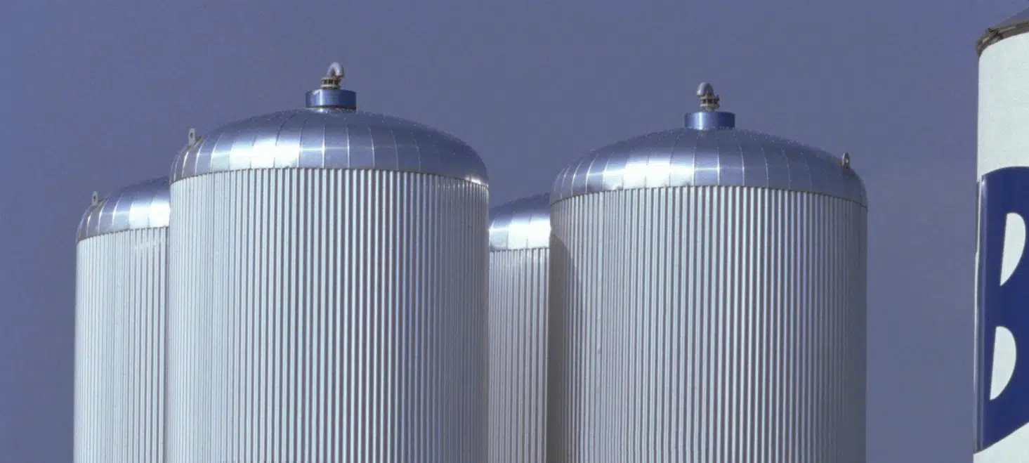
The buffer tank, or thermal storage vessel: the thermal battery of your installations
The buffer tank is a proven technology for storing heat energy, hot or cold, and releasing it at the right moment. Seemingly passive, it is in fact a key component of the hydraulic circuit: it absorbs surges, secures continuity of service and smooths power demand. EOLIOS models these tanks through CFD simulation to turn their theoretical autonomy into real, quantified and documented autonomy.
Regulate
- Absorption of flow-rate fluctuations
- Fewer demands on the chillers
- Controlled lifespan and consumption
Secure
- Thermal inertia during an interruption
- Continuity during switchovers
- Planned maintenance without downtime
Decouple
- Buffer zone between loops
- Primary-to-secondary transition
- Stable distribution to equipment
Sized to store large volumes of hot or chilled water, such a reservoir acts as a reserve of thermal energy available at any time. Coupled with heat pumps or chillers, it makes it possible to use the stored energy at peak hours, minimising consumption costs and smoothing peaks in power demand.
These tanks appear wherever a thermal demand must be smoothed: tariff peak-shaving during off-peak hours, securing cooling in data centers, backing up urban heat networks, harnessing free cooling and renewable energy, up to inter-seasonal storage. The principle is the same on the hot side as on the cold side: store when energy is available or cheap, release when demand rises.
Thermal stratification of a storage tank, the key to efficiency
Charging, discharging and thermocline of a buffer tank
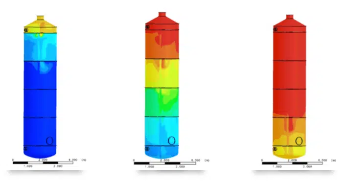
In a water storage system, energy is held in a stratified reservoir containing both hot and cold water. During charging, cold water is introduced at the bottom while an equal amount of hot water is drawn off at the top; during discharging, these flows reverse. A thermal stratification then occurs: the hot water, of low density, stays at the top; the cold water, denser, settles at the bottom.
The thermocline is the temperature transition region between the hot and cold zones. Its thickness represents the inefficiency of the reservoir: the more efficient the tank, the thinner the thermocline and the larger the truly usable volume.
As long as the inlets and outlets cause no mixing, the two zones remain separate and the energy is returned at the right temperature. It is this clean separation, and its stability over time, that gives a buffer tank all its value.
What degrades the real autonomy of a tank
On paper, a tank's autonomy is simply derived from its volume and the power to be covered. In reality it is almost always lower: three-dimensional hydraulic phenomena eat into the usable capacity well before the whole cold volume is consumed. Identifying and quantifying them is the heart of our expertise.
Mixing, thermal short-circuits and dead zones
Without careful design, the gap between theoretical and real autonomy comes from a few recurring mechanisms:
- The inertia of the incoming fluid: at high flow rate, the water injected through the inlet keeps a strong inertia and spreads rapidly over the whole height of the tank, disrupting the natural stratification.
- The suction effect of the outlet: it can create a pull that prematurely draws hot water toward the outlet, reducing the usable inertial capacity.
- Thermal short-circuits: when the fluid takes a preferential path from inlet to outlet without mobilising the whole volume, the tank's inertia is never fully used.
- Dead zones: conversely, stagnant volumes of water take no part in the storage, representing unused capacity.
Theory versus reality. It is in degraded mode, during a switchover or an interruption of cooling production, that the gap is most costly. Knowing the truly available autonomy, rather than its optimistic estimate, is what secures the installation.
Transient CFD simulation of a thermal storage tank
To capture these phenomena, we model each tank and its hydraulic circuit through CFD simulation. The approach frees itself from the simplifying assumptions of analytical methods and reproduces the real three-dimensional physics of the reservoir. It rests on three pillars.
A high-fidelity 3D model of the tank
The geometry is faithfully reconstructed from the available plans and technical documents: exact volume of the tank, precise position of each nozzle, pipe networks and connections, equipment layout. The model does not merely represent the shape: it solves the Navier-Stokes equations coupled with heat transfer to simulate the thermal and hydraulic behaviour.
Unlike a steady-state study that describes only a frozen state, the transient analysis tracks the temperature and velocity fields second by second. It anticipates the fluid's behaviour during the most critical phases, where classical calculations reach their limits.
A CFD mesh suited to steep gradients
A hybrid mesh of several million elements discretises the fluid domain, with refinement concentrated where the physics is finest: wall boundary layers, the vicinity of the nozzles, interfaces between water masses at different temperatures. This fineness reveals weak signals, such as the onset of undesirable mixing, before they affect overall performance.
Assumptions turned into usable data
The simulation makes the invisible visible and replaces estimates with quantities measurable at every point and every instant. On a storage tank, it delivers in particular:
- Stratification mapping: the evolution of the thermal front during charging and discharging, zone by zone.
- The perfect-phasing duration: the period during which the outlet temperature stays compliant, before the hot water reaches the outlet.
- The state of charge: the tracking of the mean volume temperature, an indicator of the energy still available.
- The location of defects: dead zones, short-circuits and turbulence, invisible to classical theoretical calculation.
The perfect-phasing duration is the most valuable figure: once quantified, it becomes the sizing reference for switchover procedures and for the start-up time of backup systems. Beyond that phase, the temperature rise stays controlled and predictable, allowing a reliable time map of the available autonomy.
The levers to gain inertial efficiency
Reduce the thickness of the thermocline
Stratification depends on several design levers, which the simulation lets you weigh objectively:
- the temperature loss to the environment by conduction, hence the quality of the insulation;
- the tank design, whose height-to-diameter ratio favours the layering;
- the design of the inlet and outlet diffusers, which must inject the water in laminar flow to avoid any mixing;
- the physical compartmentalisation and the choice of specific diffusers.
Act on the tank's internal architecture
Several architectural levers maximise thermal inertia without increasing the storage volume:
- Compartmentalisation: internal baffles, pierced with calibrated openings in alternating positions, guide the flow and slow the progress of the hot water. In each compartment, the hot water is forced to rise before crossing the baffle, ensuring fuller use of the cold-water volume.
- Deflectors: jet-breaker devices at the nozzles reduce the inertia of the incoming fluid and dampen turbulence at injection, limiting mixing from the first seconds.
- Tanks in series: chaining several smaller-diameter vessels reproduces the effect of compartmentalisation at installation scale. Each tank behaves as a stratification stage, extending the phasing and delaying the arrival of hot water at the outlet.
- Tank bypass: a diversion valve isolates or bypasses a tank depending on the operating phase, to control the direction and flow of charging and discharging without disturbing the stratification already achieved.
Horizontal or vertical? A vertical tank offers naturally more stable stratification. A horizontal tank favours lateral convective exchange between hot and cold water, slightly reducing stratification efficiency. This trade-off, quantified by simulation, drives the layout choice according to space constraints.
Study of the water loop & decision support
The temperature evolution of the water loop
To calculate the temperature evolution of a water loop at the tank outlet, several physical phenomena are taken into account:
- Tank energy balance: energy exchanged between the water and the tank (thermal capacity, losses, internal exchangers);
- Thermal losses: depending on the design, the insulation and the inside / outside temperature difference;
- Water flow rate in the loop: influenced by the exchanger power, the temperature difference and the hydraulic resistance;
- Heat exchange with the environment: gains or losses depending on the conditions, for example a cold airflow.
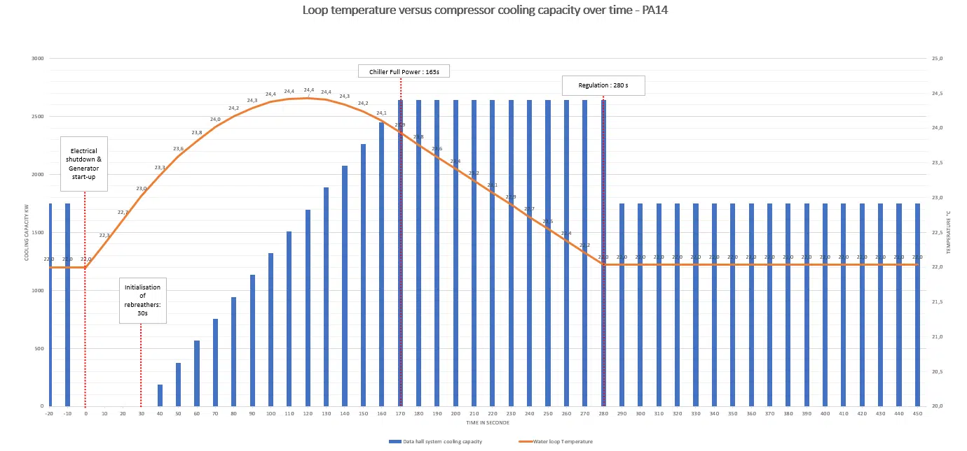
Depending on these factors and the dynamics of the loop, a mathematical model, often based on differential equations, calculates the evolution of the temperature over time.
A digital twin: decision-support tool and lasting asset
Beyond diagnosis, the study informs investment choices:
- Comparison of configurations: quantify the inertial-efficiency gain between horizontal and vertical layouts, according to site constraints.
- Cost optimisation (CAPEX): size the equipment as tightly as possible thanks to numerical precision, without the extra cost of oversizing, while meeting availability criteria.
- A reference baseline: the model is a digital twin reusable to simulate any future scenario (flow-rate change, added compartments, tank replacement) without a full new campaign.
From reactive to proactive maintenance. By anticipating the most unfavourable scenarios from the engineering stage, the operator sets alert thresholds and intervention windows with a documented safety margin, and lastingly secures the performance of the site.