
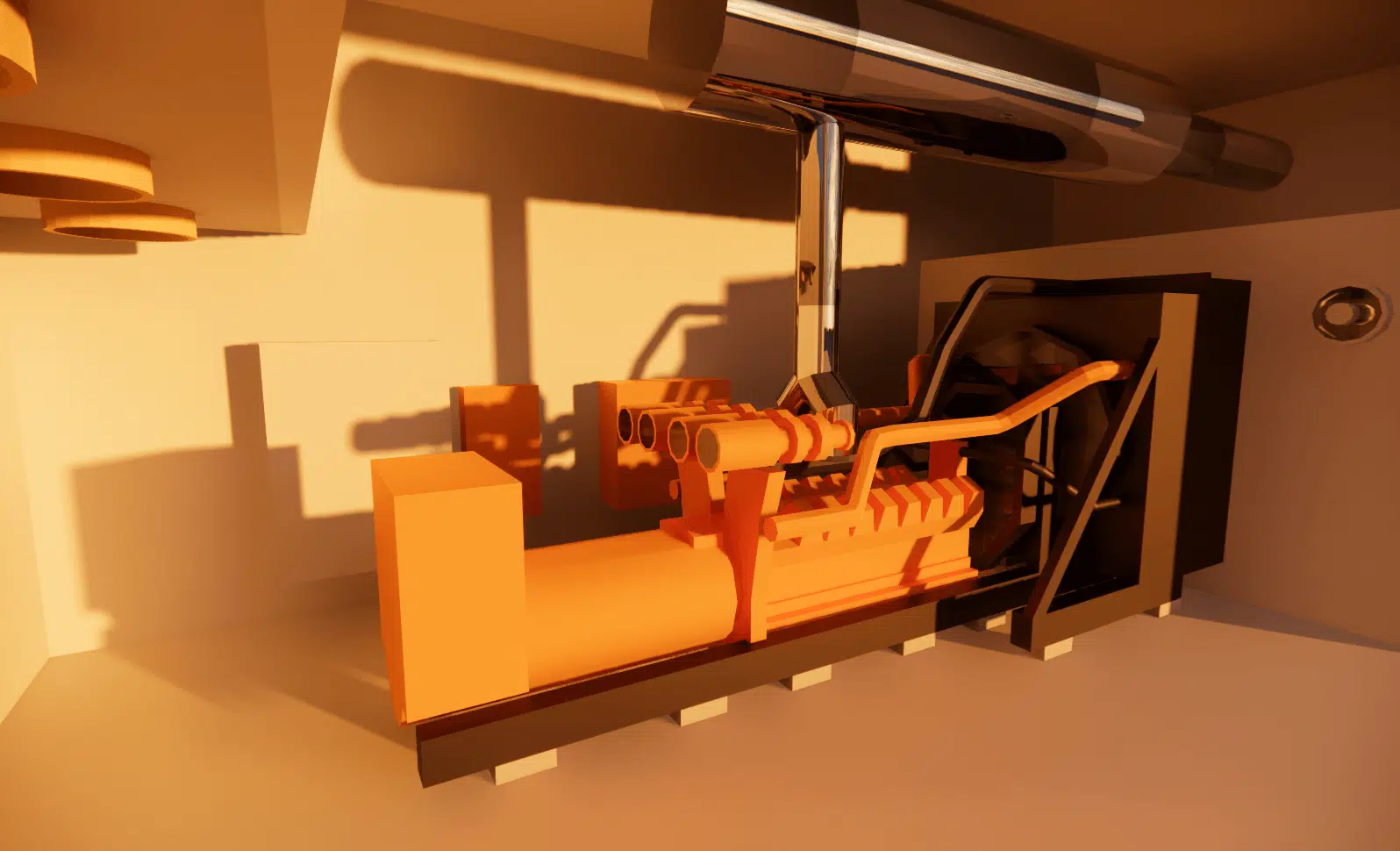
How is CFD used for generator-set rooms?
A generator set is only worth its availability on the day the grid fails. It is precisely in these extreme conditions that the room ventilation is most heavily loaded. EOLIOS secures this critical link through CFD simulation: before commissioning, we demonstrate that engine cooling, combustion air and fume evacuation meet their targets.
Study
- Pressure losses
- Natural ventilation
- NOx dispersion
Secure
- Extreme weather conditions
- Critical failure scenarios
- Bypass flows & recirculation
Optimise
- Grille layout
- Air-treatment systems
- Containerisation
Room cooling, where reliability is decided
Whether they propel a ship or power a sensitive site, diesel or gas engines must hold from arctic cold to tropical heat. In each of these environments, the room ventilation fulfils three vital missions:
- supply combustion air to the engines;
- supply fresh air to remove the unwanted heat;
- keep the room temperature within a range compatible with personnel work and components.
Too often, the airflow is sized on an average ambient temperature that masks the peaks actually encountered in operation. Our added value: reproduce the most unfavourable climatic scenarios and verify, with figures to back it up, that the engine stays within its operating range. We advise manufacturers on the combustion and cooling airflow, and cover overall ventilation, the exhaust impact study and the pressure-loss calculation of the acoustic systems.
The steps of a CFD simulation applied to the systems
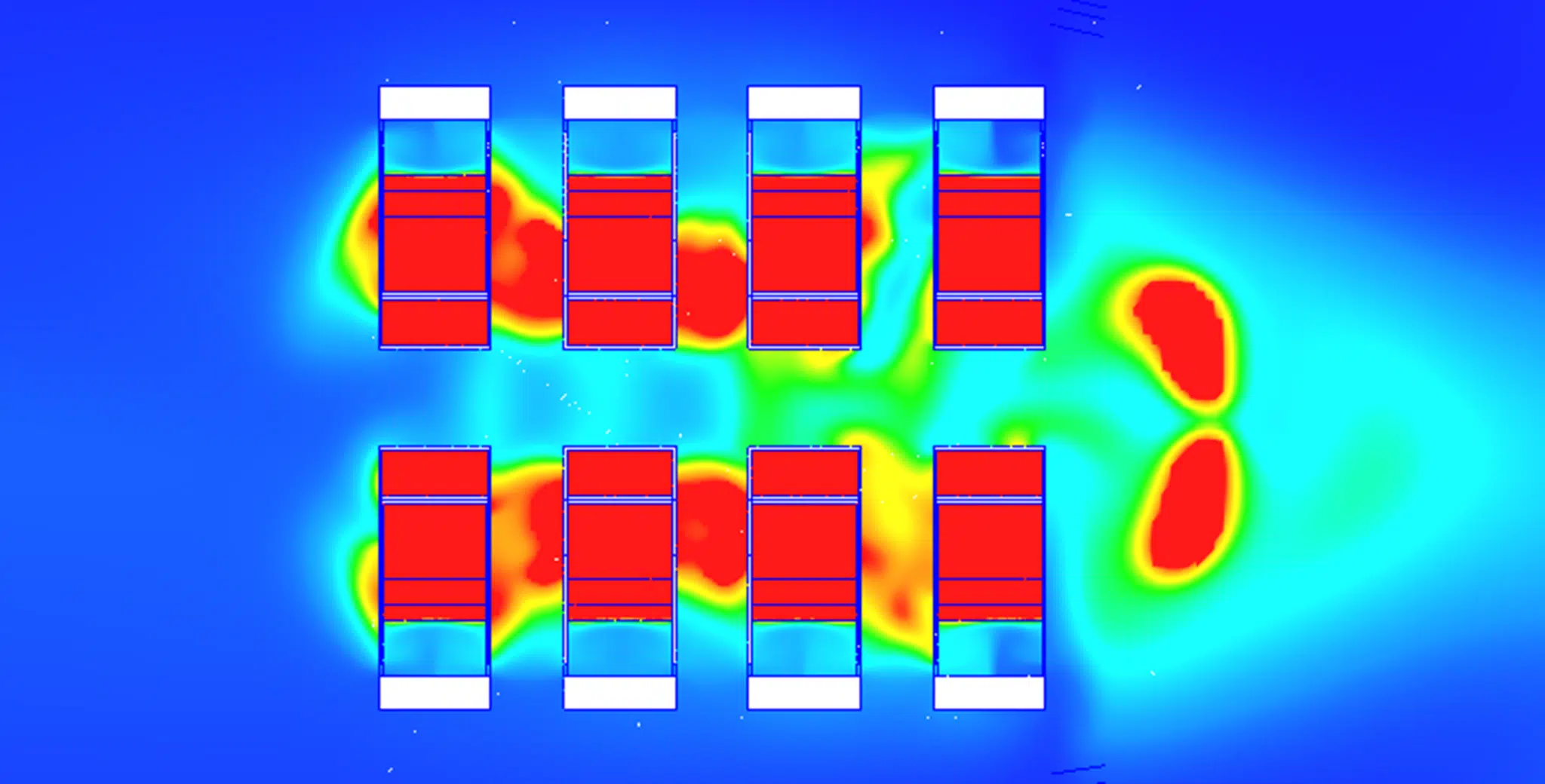
Where experimentation reaches its limits, CFD delivers a complete thermal analysis of technical rooms. Our method is proven: we first simplify the building geometry (removing details that generate too many mesh elements), then we establish the thermal profiles under the most extreme climates. The objective stays concrete: master the air inlets and outlets, channel the flow around the engine and improve its efficiency (genset). Each layout variant is compared precisely, yielding pressure, maximum intake temperature, air movements and pollutant dispersion. So many levers to decide fast and well.
Pressure losses & fan sizing
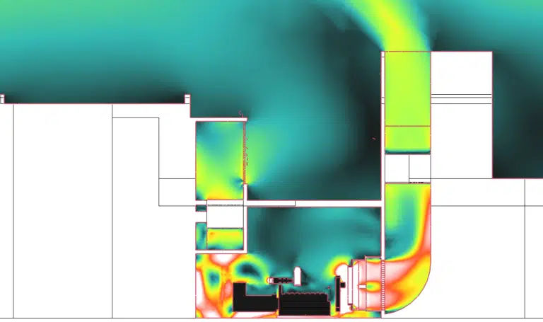
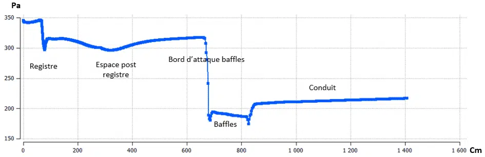
We carry out the pressure-loss studies of the acoustic baffles and the fan sizing, item by item. Losses grow exponentially with air velocity: a badly chosen silencer can choke the ventilation of the room. We identify the true contributors, foremost the louvres and acoustic baffles near the exhaust and upstream, distinguishing them from the minor resistances that are battery banks, fuel tanks, intake pipes and the exhaust stack. Result: a fan at the right size, neither oversized nor undersized.
Acoustic baffles, the main source of pressure loss
Required by noise constraints, acoustic baffles and louvres are paradoxically the first obstacle to the passage of air. Our analysis focuses on this item, because a poorly integrated acoustic treatment can on its own cut the cooling flow and trip the genset thermally. Our CFD study breaks down their contribution and arbitrates the acoustic / airflow trade-off:
- mapping of the pressure loss item by item: intake silencer, exhaust silencer, louvres and grilles;
- influence of the air velocity in the baffles, whose loss grows exponentially with flow;
- trade-off between acoustic attenuation and free area, to meet the noise target without choking the ventilation;
- selection of the fan operating point on the system curve, pressure margin included.
To the internal flow is added the wind flow over the building: the wind blowing on the room can increase the pressure loss and, above all, cause the overheated exhaust gases to recirculate towards the engine inlet.
Exhausts, pollution and contamination of HVAC fresh-air systems
A generator set secures the power supply, but its engine emits pollutants: carbon dioxide, sulphur and nitrogen oxides (NOx). Running on petrol, gas or diesel, it can heavily degrade the nearby air, especially in intensive use. Our analyses trace the complete dispersion of the exhaust gases from the discharge points and verify the absence of direct recirculation onto the fresh-air intakes (AHU) of neighbouring buildings. We quantify the pollution generated around the site and identify the intake of chimney exhausts by the fresh-air handling units that supply the living areas: the aim is to guarantee clean air to occupants and rule out any risk of the premises being contaminated by the genset fumes. You thus deliver a compliant site, with no bad surprise at handover.
Temperature rise in chimney openings
Exhaust chimneys often pass through concrete floors and walls via openings. The very hot gases then radiate towards the surrounding civil works: we calculate the temperature rise of the concrete under the thermal radiation of the chimney, in order to stay below the material's admissible thresholds and to size the necessary protections.
- modelling of the radiation from the chimney wall towards the concrete of the opening, in steady state and at peak load;
- calculation of the surface and core temperature of the concrete, compared with the material's resistance limits;
- sizing of the opening clearance, of the shield or the insulation, and of any additional ventilation;
- verification of the absence of a hot spot on neighbouring structures and equipment.
Loss of power output versus intake temperature
The power a generator set can deliver falls when the intake air warms up: beyond the reference conditions, the engine undergoes derating. We link the room inlet air temperature, calculated by CFD, to the expected electrical power loss, to guarantee that the set holds its rated power even in unfavourable conditions.
- correlation between the intake temperature from CFD and the manufacturer's derating curve;
- quantification of the power loss at temperature peaks (summer, solar impact, recirculation);
- verification that the required rated power is maintained, or sizing of the additional cooling.
Containerised generator sets: bespoke design
The container is the case where our know-how makes the biggest difference. The volume is constrained, every grille and every baffle counts, and the whole must work as well under blazing sun as in severe cold. We design and validate these packaged sets by CFD simulation, before manufacturing, to avoid costly rework on site.
Testing every weather, including the most extreme
A container travels and is installed anywhere. We therefore test each design in several climatic scenarios, from arctic cold to tropical heat, to guarantee engine cooling in the most unfavourable envelope:
- Extreme climates: high and low ambient temperatures, wind and container orientation combined with the engine peak load.
- Solar impact: radiation heats the walls and roof, which raises the internal temperature and the intake temperature; we quantify this input and its effect on the useful flow.
- External recirculation: we verify that the wind does not wash the hot exhaust gases back towards the container intake grilles.
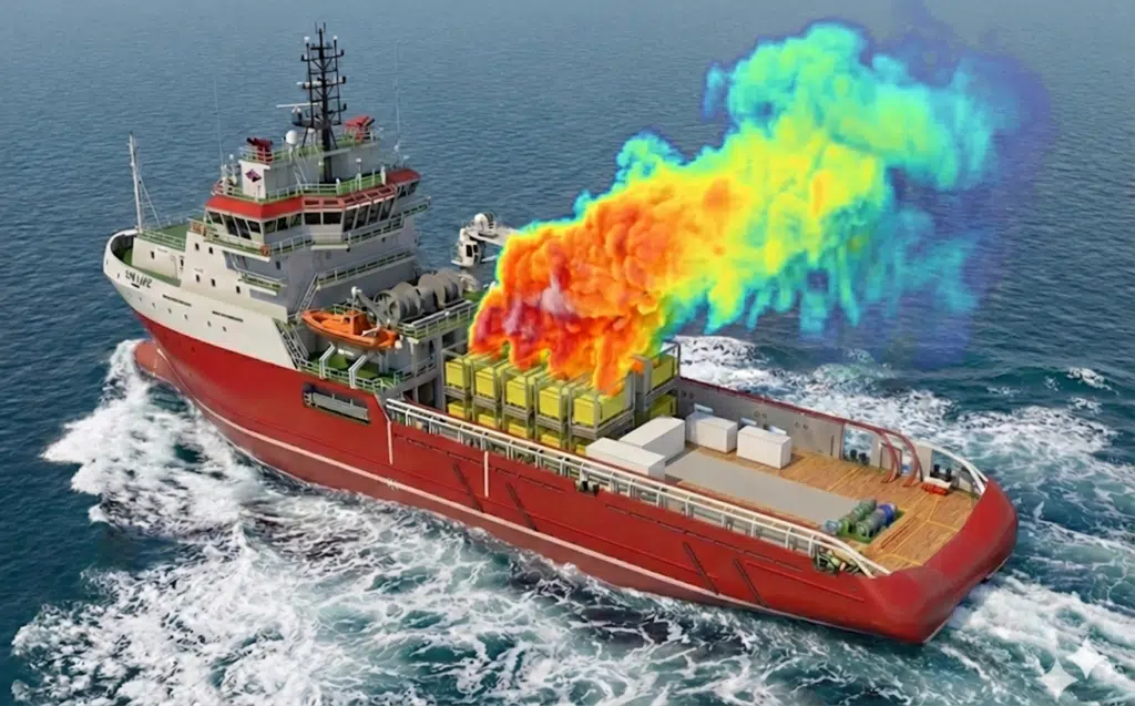
An envelope drawn as tightly as possible
From these results, we optimise the layout of the inlet and discharge grilles, the routing of the air around the engine and the alternator, as well as the sizing of the fans against the pressure losses of the acoustic baffles. You obtain a container validated numerically, reliable in all its operating conditions and delivered without a costly physical test campaign.
A team of engineers seasoned in generator sets
At EOLIOS, generator sets are part of our daily work. Our engineers know the sizing constraints, from engine cooling to the pressure losses of acoustic baffles, and act as genuine sources of proposals: we do not just deliver calculation results, we propose concrete solutions to make your installation reliable.
Used to working with manufacturers, design offices and operators, we speak the same technical language as your teams and secure your choices, from the design file through to commissioning.